


Description
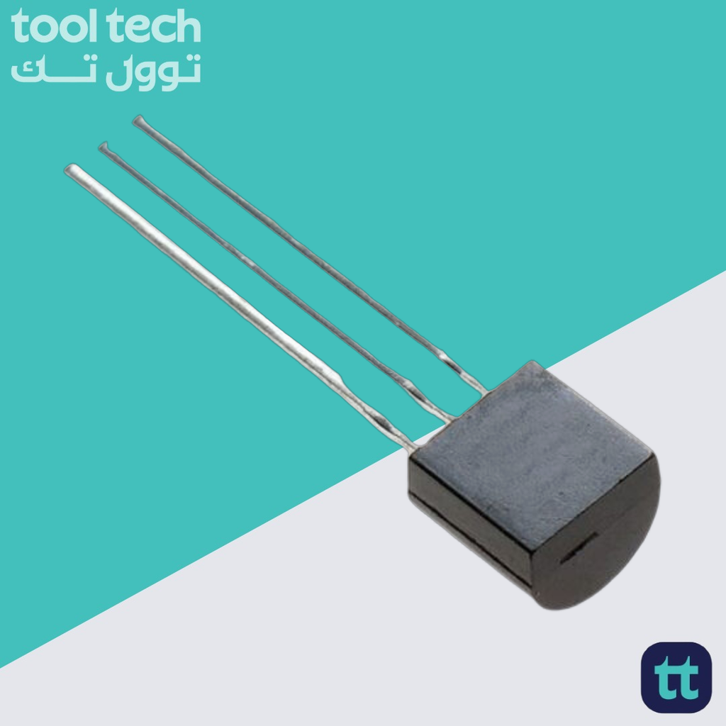
The 2N5551 is a high-voltage, low-power NPN bipolar junction transistor (BJT). It is a “workhorse” in electronic design, particularly known for its ability to handle voltages significantly higher than standard small-signal transistors like the BC546 or 2N2222.
Key Specifications
| Parameter | Symbol | Rating |
| Collector-Emitter Voltage | $V_{CEO}$ | 160V |
| Continuous Collector Current | $I_C$ | 600mA (0.6A) |
| Power Dissipation | $P_D$ | 625mW |
| DC Current Gain | $h_{FE}$ | 80–250 (at 50mA) |
| Transition Frequency | $f_T$ | 100MHz |
Why Choose the 2N5551?
-
High Voltage Handling: With a $V_{CEO}$ of 160V, this transistor is designed for circuits where high supply rails are present, such as line-powered electronics, high-voltage driver stages, or specialized power supply control circuits.
-
Versatile Current Capacity: While it is a signal transistor, its 600mA rating is quite high for the TO-92 package. It can drive small relays, indicator lamps, or act as a gate driver for power MOSFETs.
-
High-Speed Operation: With a transition frequency ($f_T$) of 100MHz, it is well-suited for switching applications and high-frequency signal amplification.
Typical Applications
-
High-Voltage Amplification: Often used in audio output stages or as a voltage amplifier in CRT displays and specialty test equipment.
-
Level Shifting: Frequently used to translate low-voltage microcontroller logic (e.g., 3.3V) up to a higher voltage rail (e.g., 50V–100V) to switch a downstream power component.
-
Telephone Circuits: Traditionally used in telephony applications due to the high voltage tolerance required for ring signals and line voltage.
Implementation Guidelines
-
Thermal Management: Being a TO-92 (plastic) package, it has limited thermal dissipation (625mW). If you are switching near the 600mA limit, the device will heat up significantly. Ensure there is adequate airflow and do not subject it to continuous maximum-current loads.
-
Base Drive: It is a standard BJT, not a Darlington. You need to supply sufficient base current to achieve saturation. A common rule of thumb is to set the base current to be about $1/10^{th}$ of the expected collector current to ensure the device is fully turned “ON” (in saturation).
-
Pinout Awareness: When viewing the flat side of the transistor with the leads pointing down, the pins are typically Emitter (1), Base (2), Collector (3) from left to right. Always double-check the datasheet for your specific manufacturer, as some variants can differ.













Reviews
There are no reviews yet.