


Description
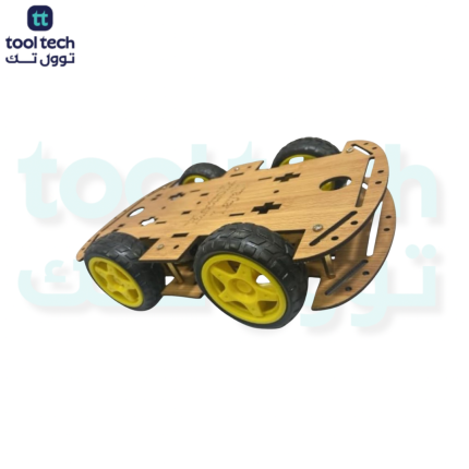
The 4WD Robotic Chassis with Encoders and Fixed Frame is a versatile, high-traction platform designed for building autonomous robot vehicles. While many versions of this chassis are made from transparent acrylic, wooden (often MDF or plywood) versions are popular in educational settings because they are easy to customize, drill, or paint.
Key Components & Design
-
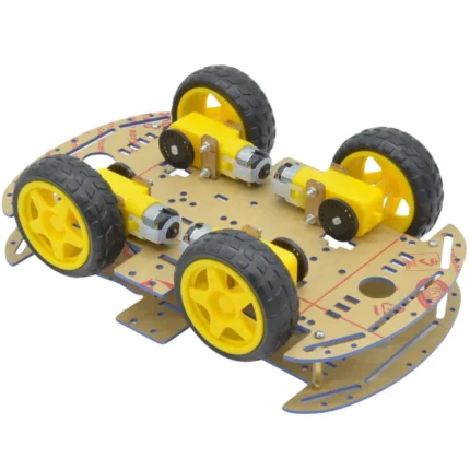
4WD System: Uses four DC gear motors (typically 3V–6V “TT” or “BO” motors) to provide excellent torque and traction, allowing the robot to navigate uneven surfaces or carry heavier payloads than a standard 2WD chassis.
-
Dual-Platform “Fixed Frame”: The chassis typically features two stacked plates. This “double-decker” design is excellent for organization:
-
Lower Level: Usually holds the battery pack and the motors.
-
Upper Level: Provides a clean, dedicated space to mount your microcontroller (like an Arduino or Raspberry Pi), motor drivers, and various sensors.
-
-
Speed Encoders: The kit includes slotted encoder discs that attach to the motor shafts. When paired with an optical sensor (usually sold separately or included), these allow your robot to track how far it has traveled and monitor the speed of each wheel independently—essential for precision turning and path planning.
Technical Specifications
-
Chassis Material: Laser-cut wood (or acrylic), providing a sturdy, pre-drilled frame with mounting holes for standard components.
-
Motors: 4 x DC gear motors (usually 100–200 RPM at 6V).
-
Wheels: 4 x high-grip rubber tires with plastic rims (typically 65mm in diameter).
-
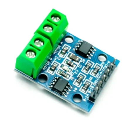
Expandability: The pre-cut holes are designed to accommodate common robotics modules like ultrasonic distance sensors, line-tracking sensors, and motor driver boards (e.g., L298N).
Common Applications
-
Autonomous Navigation: Ideal for building obstacle-avoidance robots that use sensors to detect walls or objects.
-
Precision Robotics: The inclusion of encoders makes this an excellent platform for projects requiring “odometry” (calculating the robot’s position based on wheel rotations), such as maze-solving or drawing specific shapes.
-
STEM Education: A favorite in classrooms for teaching electronics, motor control, and PID (Proportional-Integral-Derivative) logic.
Pro-Tips for Assembly
-
Motor Wiring: Since this uses four motors, you will typically need to wire the two left-side motors together and the two right-side motors together (or use a 4-channel motor driver) to control them from your board.
-
Encoder Calibration: When installing the encoders, ensure the optical sensor is perfectly aligned with the slots in the disc. If the sensor is too far away or misaligned, it will fail to count the rotations correctly.
-
Frame Rigidity: Because it is a “fixed frame,” ensure all spacers (usually included in the kit) are tightened securely to prevent the chassis from wobbling, which can lead to inaccurate sensor readings.

















Reviews
There are no reviews yet.