

Description
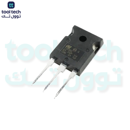
The IRF9530N is a P-Channel Power MOSFET designed for high-speed switching applications. Unlike the Darlington transistors we have discussed previously, this is a Field-Effect Transistor (FET).
The fundamental difference is that while Darlingtons are current-controlled devices (requiring a constant base current to stay “on”), the MOSFET is voltage-controlled. Once the gate voltage is set relative to the source, the MOSFET creates an electric field that allows conduction, requiring negligible gate current to maintain that state.
Key Specifications
| Parameter | Symbol | Rating |
| Drain-Source Voltage | $V_{DS}$ | -100V |
| Continuous Drain Current | $I_D$ | -12A |
| Pulsed Drain Current | $I_{DM}$ | -48A |
| Gate-Source Threshold Voltage | $V_{GS(th)}$ | -2V to -4V |
| Static Drain-Source On-Resistance | $R_{DS(on)}$ | 0.20 $\Omega$ |
| Power Dissipation | $P_D$ | 88W |
Understanding the P-Channel MOSFET
Because this is a P-Channel device, it is primarily used for High-Side Switching.
-
How it turns ON: The MOSFET turns on when the Gate voltage is pulled lower than the Source voltage. If your load is powered by a 12V rail (connected to the Source), the MOSFET will turn on when the Gate voltage is pulled significantly below 12V (ideally toward 0V).
-
Efficiency: Note the $R_{DS(on)}$ of 0.20 $\Omega$. At a current of 10A, the power loss ($P = I^2 \times R$) would be $10^2 \times 0.20 = 20W$. This is significantly more efficient than a Darlington transistor, which would have a much higher voltage drop, making this MOSFET a superior choice for high-current applications where heat must be minimized.
Essential Implementation Notes
-
Gate Voltage Considerations: To fully “open” the MOSFET channel and reach the low $R_{DS(on)}$ rating, the $V_{GS}$ should typically be driven to -10V. If you are using a 3.3V or 5V microcontroller, you cannot switch a 12V or 24V rail directly; you will need a small NPN transistor (like a 2N2222) to act as a level shifter to pull the MOSFET gate to ground.
-
Gate Capacitance: MOSFETs have internal gate capacitance. While they are “voltage-controlled,” you need to charge this capacitance to switch the device. Rapidly switching at high frequencies requires a driver circuit capable of sourcing/sinking current into the gate.
-
No Flyback Required (Internal Diode): MOSFETs have an internal body diode. While this provides some protection for inductive loads, adding a dedicated fast-recovery diode in parallel with the load is still recommended for high-power motors or solenoids.
Comparison to Darlington Transistors
-
Control: Voltage-controlled (MOSFET) vs. Current-controlled (Darlington).
-
Power Efficiency: MOSFETs generally dissipate much less power at high currents due to their resistive nature ($R_{DS(on)}$) compared to the constant diode voltage drop of a Darlington.
-
Complexity: MOSFETs require careful attention to $V_{GS}$ levels to prevent operating in the “linear region,” where they can overheat rapidly.













Reviews
There are no reviews yet.