

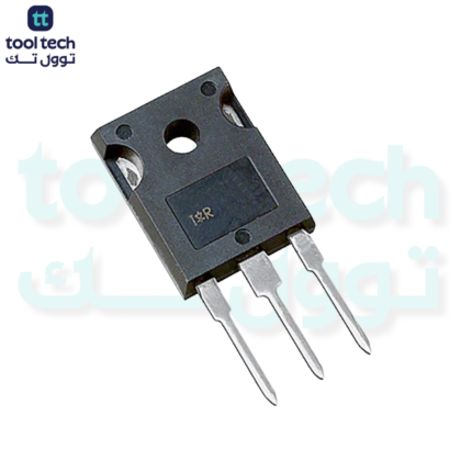
Description
The IRFP450 is a high-voltage, high-current N-Channel Power MOSFET. Similar to the IRFP460, it is designed for demanding power switching applications such as switch-mode power supplies (SMPS), high-voltage DC-DC converters, and motor speed control.
Key Specifications
-
Transistor Type: N-Channel MOSFET
-
Drain-Source Voltage ($V_{DS}$): 500 V
-
Continuous Drain Current ($I_D$): 14 A (at $25^{\circ}\text{C}$)
-
On-Resistance ($R_{DS(on)}$): $0.4 \ \Omega$ (Max)
-
Power Dissipation ($P_D$): 190 W
-
Package Type: TO-247
Pinout Configuration
When looking at the front of the TO-247 package with the metal tab at the top and the pins pointing down, the pins from left to right are:
-
Gate (G)
-
Drain (D)
-
Source (S)
Comparison: IRFP450 vs. IRFP460
While both are 500V power MOSFETs in the TO-247 package, the IRFP460 is slightly more robust in terms of current handling and on-resistance.
| Feature | IRFP450 | IRFP460 |
| Max Current ($I_D$) | 14 A | 20 A |
| On-Resistance ($R_{DS(on)}$) | $0.4 \ \Omega$ | $0.27 \ \Omega$ |
| Power Dissipation ($P_D$) | 190 W | 280 W |
Note: The IRFP450 is often chosen when the higher current capacity of the IRFP460 is not required, as it may be more cost-effective or more readily available depending on the supply chain.
Usage Best Practices
-
Gate Drive Circuitry: Because the gate acts as a capacitor, you cannot drive it directly from a microcontroller pin if you need fast switching. Using a dedicated MOSFET gate driver IC (such as the TC4420 or IR2110) will ensure the MOSFET switches fully “ON” and “OFF” rapidly, minimizing heat generated during the transition.
-
Thermal Management: With a power dissipation rating of 190W, a large, finned heatsink is critical. Always ensure clean mounting, use high-quality thermal interface material (thermal paste or pads), and provide adequate airflow if operating near rated currents.
-
Safe Operating Area (SOA): High-voltage MOSFETs are prone to “second breakdown” or parasitic oscillations. Ensure your gate signal is clean (no ringing) and that you use a small gate resistor (e.g., $10 \ \Omega$ to $47 \ \Omega$) close to the gate pin to dampen high-frequency oscillations.
-
Flyback Protection: When switching inductive loads, the high voltage generated by the collapsing field can easily exceed 500V. A fast-recovery snubber circuit or a TVS diode is recommended to protect the drain-source junction.













Reviews
There are no reviews yet.