


Description
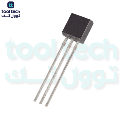
The TIP126 is an 80V, 5A PNP Darlington transistor. It occupies the “middle ground” in the TIP12x series, providing a higher voltage tolerance than the TIP125 (60V) while sharing the same current capacity as both the TIP125 and the higher-voltage TIP127 (100V).
It is a specialized choice when your supply voltage exceeds 60V but does not require the full 100V overhead of the TIP127.
Key Specifications
| Parameter | Symbol | Rating |
| Collector-Emitter Voltage | $V_{CEO}$ | -80V |
| Continuous Collector Current | $I_C$ | -5A |
| Peak Collector Current | $I_{CM}$ | -8A |
| Collector-Emitter Saturation Voltage | $V_{CE(sat)}$ | -2.0V (at 3A) |
| DC Current Gain | $h_{FE}$ | 1,000 min (at 3A) |
| Power Dissipation | $P_D$ | 65W |
The TIP12x Series: Selection Guide
Understanding where the TIP126 fits into the family helps in selecting the most cost-effective and reliable component for your voltage rail:
| Part Number | VCEO | IC | Primary Use |
| TIP125 | 60V | 5A | General 12V/24V applications. |
| TIP126 | 80V | 5A | Applications with 36V/48V rails. |
| TIP127 | 100V | 5A | High-voltage industrial applications. |
Practical Design Considerations
-
High-Side Switching (Level Shifting): Because this is a PNP device, the emitter is tied to the positive rail. If you are using a 3.3V or 5V logic signal to switch a 48V rail, the base voltage must be pulled low enough to trigger conduction. A simple NPN transistor (like a 2N3904) is highly recommended as a driver to bridge the voltage gap between your controller and the TIP126 base.
-
Thermal Dissipation: Like all Darlington pairs, the internal dual-transistor structure causes a higher voltage drop than a standard single BJT. At 5A, the $V_{CE(sat)}$ drop is significant. If your application runs at continuous high currents, forced air cooling or a substantial heatsink is necessary to keep the junction temperature below the maximum limit.
-
Complementary Logic: The TIP126 is designed to work in tandem with the TIP121 (NPN). Using these as a matched set allows for the design of efficient Class-B or Class-AB audio amplifiers and motor H-bridge drivers where both “push” and “pull” capabilities are required.
Troubleshooting Tips
-
Excessive Heat: If the transistor runs extremely hot at low current, you may not be providing enough base current to fully saturate the device. Check your base resistor value; if the base is not fully turned “on,” the transistor stays in the linear (resistive) region, causing it to dissipate excessive power.
-
Flyback Protection: When using the TIP126 to switch motors, solenoids, or relays, always include a protection diode across the load. Even though the device is robust, back-EMF spikes can exceed the 80V rating and destroy the junction instantly.














Reviews
There are no reviews yet.