


Description
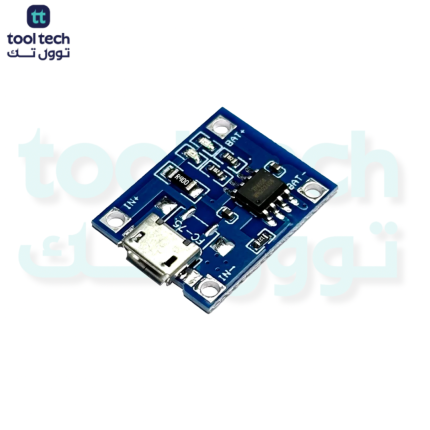
TP4056 Battery Charger with Integrated Boost Converter
The TP4056 with Boost is a versatile 2-in-1 power management module. It combines a dedicated TP4056 lithium battery charging circuit with a DC-DC boost converter. This module is designed to charge a 3.7V Lithium-ion cell (via Micro/USB-C) and simultaneously provide a stable 5V output to power your electronics.
Technical Specifications
| Feature | Specification |
| Charging IC | TP4056 |
| Boost Converter Output | Typically 5V (Adjustable on some models) |
| Input Voltage | 5V (via USB port) |
| Charging Current | Up to 1A (adjustable via resistor) |
| Battery Voltage | 3.7V Li-ion / Li-Po |
| Protection | Overcharge, Over-discharge, Over-current |
| Efficiency | ~85%–90% (Boost section) |
How It Works
This module serves two primary functions:
-
Charging (TP4056): When connected to a 5V USB power source, the TP4056 chip charges the attached 3.7V battery using the standard Constant Current/Constant Voltage (CC/CV) profile.
-
Boosting: The onboard DC-DC boost converter takes the 3.7V from the battery and steps it up to a stable 5V, which is then provided at the output pins or USB port to power your project.
Key Features
-
Integrated Protection: Includes built-in protection for the battery, cutting off charging at 4.2V and discharging at 2.4V–3.0V, which is essential for cell longevity.
-
Dual Status LEDs: Most modules feature two LEDs—one to indicate charging status (Red) and one to indicate that charging is complete (Blue/Green).
-
Space-Saving: By combining the charger and booster on a single board, you significantly reduce the footprint of your project’s power management system.
-
Self-Regulating: The boost converter maintains a steady 5V output even as the battery voltage drops during use.
Important Installation & Safety Guidelines
-
Polarity Matters: Always double-check the battery polarity (B+ and B-) before soldering. Reverse polarity can permanently damage the TP4056 chip.
-
Boost Load Limits: While the TP4056 handles 1A charging, the boost converter often has a lower current limit (typically 0.5A to 1A). Do not attempt to pull high current (like driving heavy motors) directly from the boost output.
-
Heat Management: The TP4056 chip will get warm during the 1A charging cycle. This is normal, but ensure the board is not trapped in an airtight enclosure while charging.
-
Simultaneous Use: Some versions of this board are designed for “pass-through” charging, meaning you can charge the battery and power the load at the same time. Check your specific module’s datasheet, as some cheaper variants may not support this reliably.














Reviews
There are no reviews yet.