
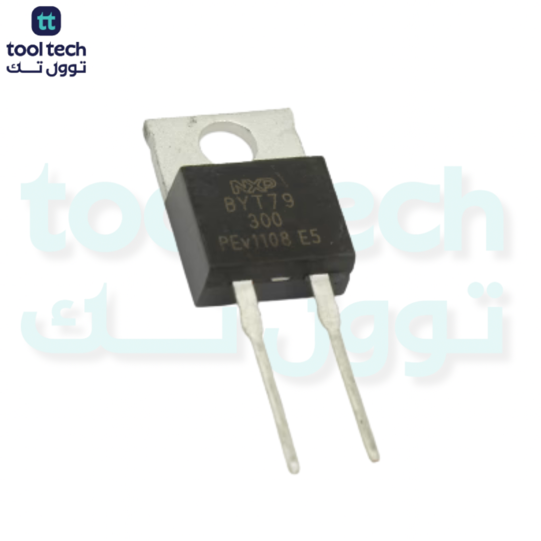


Description
Technical Specifications (Typical for 300V/14A Ultra-Fast)
| Parameter | Rating |
| Peak Repetitive Reverse Voltage ($V_{RRM}$) | 300 V |
| Average Rectified Forward Current ($I_{F(AV)}$) | 14 A – 15 A |
| Reverse Recovery Time ($t_{rr}$) | < 60 ns |
| Forward Voltage Drop ($V_F$) | ~1.2 V (at 14A) |
| Package Type | TO-220AC or TO-263 (D2PAK) |
Why “Ultra-Fast” Matters
In high-frequency circuits (switching above 20 kHz), standard rectifier diodes (like the 1N4007) are too slow. They take too long to stop conducting when the voltage reverses, leading to a “reverse recovery current” spike. This causes:
-
High Power Loss: The diode dissipates significant heat during the recovery phase.
-
Electromagnetic Interference (EMI): The sharp current spikes create noise that can interfere with other components.
-
Stress on Switching Transistors: The recovery current puts extra strain on your MOSFETs or IGBTs.
Key Design Considerations
-
Thermal Management: At 14A, even with low switching losses, the conduction loss ($P = V_F \times I_{avg}$) will be around 15–18 Watts. You must use a substantial heatsink. Ensure the diode is mounted with thermal grease or a thermal pad to keep the junction temperature within safe limits.
-
Voltage Margin: A 300V rating is suitable for circuits where the peak operating voltage stays well below 300V. If your circuit has high inductive spikes (common in motors and transformers), you must ensure your “snubber” circuits are effective, or choose a diode with a higher voltage rating to prevent “avalanche” breakdown.
-
Mounting: * TO-220: The most common through-hole package for this power level. It features a metal tab that acts as the thermal interface.
-
TO-263 (D2PAK): The surface-mount version. It requires a large copper pour on the PCB to act as a heatsink.
-
Typical Applications
-
Output Rectification: Converting high-frequency AC from a transformer secondary back to DC in SMPS (Switch Mode Power Supplies).
-
Motor Control: Acting as a “freewheeling” diode in PWM-controlled DC motor circuits to provide a path for inductive current during the “off” cycle of the transistor.
-
Inverters: Used in stages where high-speed switching is required to maintain efficiency and reduce harmonic distortion.
Selection Checklist
-
Check the $t_{rr}$: Ensure the specific $t_{rr}$ matches your switching frequency. A lower $t_{rr}$ is always better for efficiency but may be more expensive.
-
Verify Junction Temperature ($T_J$): Check the datasheet to ensure the diode can operate at your expected ambient/heatsink temperature.
-
Circuit Topology: If you are building a full-bridge or half-bridge, ensure your layout minimizes lead length (parasitic inductance) to take full advantage of the diode’s ultra-fast switching characteristics.













Reviews
There are no reviews yet.