

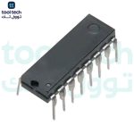
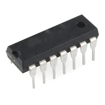
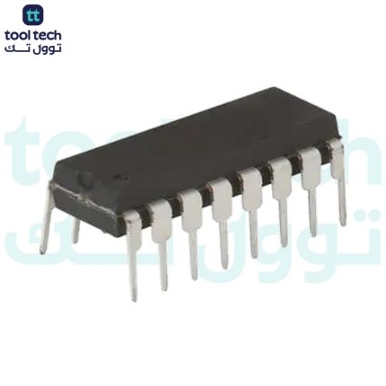
Description
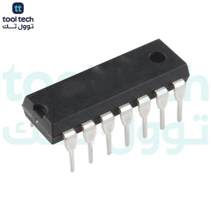
Description for the CD40174B
Cd40174B consists of six identical ’D’-type flip-flops having independent DATA inputs. The CLOCK and CLEAR inputs are common to all six units. Data are transferred to the Q outputs on the positive-going transition of the clock pulse. All sic flip-flops are simultaneously reset by a low level on the CLEAR input.
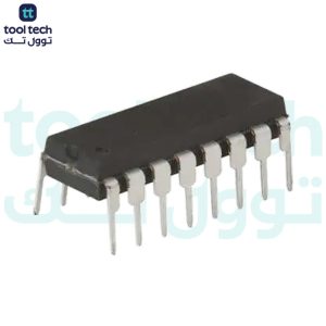
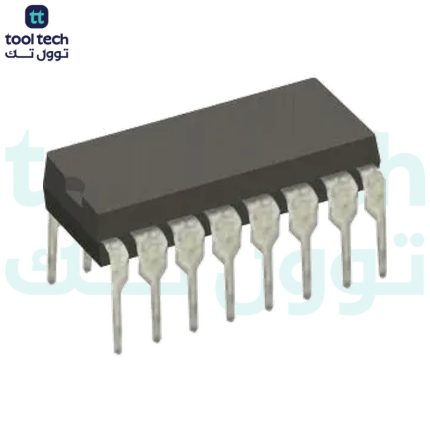
The CD40174B types are supplied in 16-lead hermetic dual-in-line ceramic packages (F3A suffix), 16-lead dual-in-line plastic packages (E suffix), 16-lead small-outline packages (M, M96, MT and NSR suffixes), and 16-lead thin shrink small-outline packages (PW and PWR suffixes).
Features for the CD40174B
5-V, 10-V, and 15-V parametric ratings
Standardized, symmetrical output characteristics
100% tested for quiescent current at 20 V
Maximum input current of 1 µA at 18 V over full package-temperature range; 100 nA at 18 V and 25°C
Noise margin (full package-temperature range) =
1 V at V
DD
= 5 V
2 V at V
DD
= 10 V
2.5 V at V
DD
= 15 V
CD40174 Pinout Diagram
CD40174 Pin Description
Pin No
Pin Name
Description
1
CLEAR’
Invert Clear Pin
2
Q1
Output Of D Flip Flop Q1
3
D1
Input Of D Flip Flop 1
4
D2
Input Of D Flip Flop 2
5
Q2
Output Of D Flip Flop Q2
6
D3
Input Of D Flip Flop 3
7
Q3
Output Of D Flip Flop Q3
8
VSS
Supply Voltage
9
CLOCK
Clock Pin
10
Q4
Output Of D Flip Flop Q4
11
D4
Input Of D Flip Flop 4
12
Q5
Output Of D Flip Flop Q5
13
D5
Input Of D Flip Flop 5
14
D6
Input Of D Flip Flop 6
15
Q6
Output Of D Flip Flop Q6
16
VDD
Drain Voltage
Applications
Shift Registers
Buffer/Storage Registers
Pattern Generators
CD40174B Datasheet













Reviews
There are no reviews yet.