

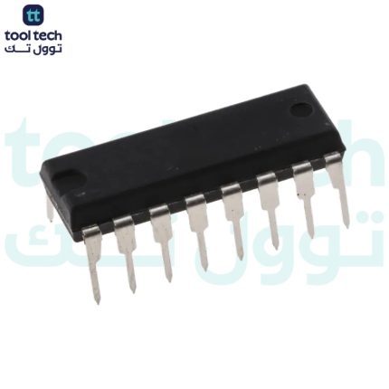
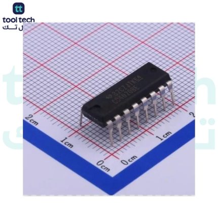
Description
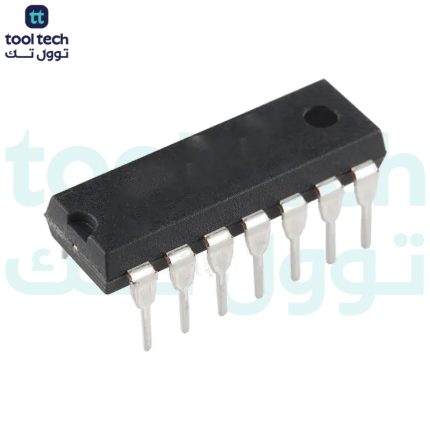
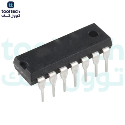
CD4518 IC
is a BCD Up counter consisting of two individual synchronous Up counters. The IC is made from D-type flip-flops and has an interchangeable CLOCK and ENABLE pin. Upcounter IC has various applications and can be used for timing-related projects.
CD4518 Pinout Configuration
The CD4518 IC has 16 pins in total. The table below can be referred to understand the pin configuration of the IC.
Pin Number
Pin Type
Pin Description
1
Clock A
Clock Input A
2
Enable A
Enable line A
3
Q1A
Counter A
4
Q2A
Counter A
5
Q3A
Counter A
6
Q4A
Counter A
7
Reset A
To Reset counter A
8
VSS
Ground
9
Clock B
Clock Input B
10
Enable B
Enable line B
11
Q1B
Counter B
12
Q2B
Counter B
13
Q3B
Counter B
14
Q4B
Counter B
15
Reset B
To Reset Counter B
16
VDD
Positive supply Input
Technical Specifications
Physical
Case/Package
PDIP
Contact Plating
Gold
Mount
Through Hole
Number of Pins
16
Technical
Direction
Unidirectional
Frequency
8 MHz
Logic Function
Counter
Max Operating Temperature
125 °C
Max Supply Voltage
18 V
Min Operating Temperature
-55 °C
Min Supply Voltage
3 V
Number of Bits
4
Number of Bits per Element
4
Number of Channels
2
Number of Circuits
2
Number of Elements
2
Number of Gates
2
Propagation Delay
650 ns
Quiescent Current
100 µA
Reset
Asynchronous
Sync/Async
Synchronous
Turn-On Delay Time
560 ns
Dual BCD Up Counter IC Working
The CD451 Up counter consists of two identical synchronous 4-stage counters. The image below shows the logic circuit of the BCD Up counter.
The counter stages are the D-type flip-flops having interchangeable CLOCK and ENABLE lines for incrementing the positive or negative-going transition, For the operation of a single unit, the ENABLE input is kept HIGH and the counter advances each positive-going transition of the CLOCK. The RESET lines clear out the HIGH levels.
Applications
Here are some of the applications of the CD4518 IC.
Pulse counter
Counter circuits
Multistage Ripple Counting
Timing related projects
4018 Datasheet














Reviews
There are no reviews yet.