



Description
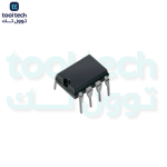
The 24C04 is a 4-kilobit (512-word x 8-bit) Serial EEPROM. Like the 24C16, it is designed with a unique internal structure that utilizes the slave address bits to manage the memory capacity, making it a “mid-sized” non-volatile memory solution.
Key Specifications
-
Capacity: 4K bits (512 bytes)
-
Interface: $I^2C$ (2-wire serial protocol)
-
Operating Voltage: 1.7V to 5.5V
-
Write Cycle Time: $\le 5\text{ms}$
-
Endurance: 1,000,000 write cycles
-
Page Size: 16 bytes
Pinout Configuration (8-Pin)
-
A0: Internally Unconnected (NC) or ignored.
-
A1: Device Address Input (sets the 2nd bit of the slave address).
-
A2: Device Address Input (sets the 3rd bit of the slave address).
-
VSS: Ground.
-
SDA: Serial Data I/O.
-
SCL: Serial Clock Input.
-
WP: Write Protect.
-
VCC: Power Supply.
Addressing and Memory Blocks
The 24C04 is organized into two 256-byte blocks. Because of this, it uses a slightly different addressing approach than the 24C02:
-
Block Select: The device address byte includes a bit (often referred to as $P0$ or $B0$) that selects between the first 256 bytes (Block 0) and the second 256 bytes (Block 1).
-
Flexibility: Unlike the 24C16, the 24C04 still allows for some device selection via the A1 and A2 pins. This means you can typically have up to 4 of these devices on the same $I^2C$ bus.
Comparison Table
| Feature | 24C02 | 24C04 | 24C16 |
| Capacity | 256 Bytes | 512 Bytes | 2,048 Bytes |
| Device Selection | Pins A0-A2 | Pins A1-A2 | Not supported |
| Block Selection | N/A | Included in Address | Included in Address |
Common Applications
-
Configuration Storage: Ideal for devices needing slightly more space than a 24C02, such as more complex calibration profiles.
-
Event Logging: Storing limited history of device usage or error codes.
-
Parameter Sets: Holding multiple “modes” of operation for microcontroller-based systems.
Essential Design Requirements
-
Pull-up Resistors: SDA and SCL pins are open-drain and require $4.7\text{k}\Omega$ to $10\text{k}\Omega$ pull-up resistors to VCC.
-
Decoupling: Use a $0.1\mu\text{F}$ capacitor between VCC and VSS to ensure stable power delivery, which is vital during the sensitive “Write” cycle.
-
Write Protect (WP): To enable normal operation, connect the WP pin to ground. If the pin is left floating, behavior can be unpredictable, so a hard connection is always best.












Reviews
There are no reviews yet.