


Description
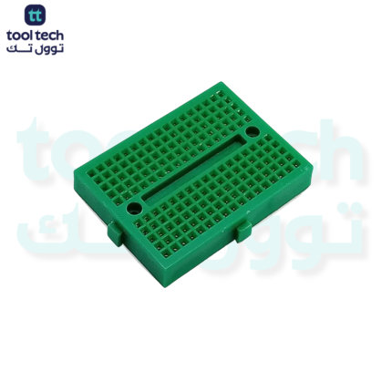
MB102 Solderless Breadboard – 830 Tie Points
The MB102 is the industry-standard breadboard for electronics prototyping. Featuring 830 tie points, it provides the perfect balance between board size and component capacity, making it the go-to choice for students, hobbyists, and professional engineers testing digital and analog circuits.
Technical Specifications
| Feature | Specification |
| Total Tie-Points | 830 |
| Configuration | 630 terminal points + 200 power distribution points |
| Power Rails | 2 dedicated vertical power rails (each split into two) |
| Dimensions | 16.5cm x 5.5cm x 0.85cm |
| Material | ABS plastic (housing), Nickel-plated phosphor bronze (contacts) |
| Mounting | Self-adhesive foam backing |
| Interlocking | Yes (side slots for expansion) |
| Wire Compatibility | 20–29 AWG (Solid-core wire recommended) |
Key Features
-
Dual Power Rails: Features two independent vertical power distribution rails. These are ideal for running dual-voltage circuits (e.g., 3.3V and 5V) or separating digital/analog ground planes to reduce noise.
-
Large Prototyping Area: The central terminal area is designed to accommodate multiple integrated circuits (ICs), microcontrollers, and various peripheral components simultaneously.
-
Interlocking Design: The board includes side tabs that allow you to snap multiple MB102 units together, creating a massive prototyping surface for complex projects.
-
Professional Contact Quality: The nickel-plated spring clips are designed for long-term use, maintaining low contact resistance even after thousands of insertion cycles.
Best Practices for Use
-
Wire Selection: Always use solid-core jumper wires (22–24 AWG). Stranded wires should be avoided as they can fray and potentially damage the internal phosphor bronze clips, leading to intermittent connections.
-
Power Distribution: Note that the side power rails are often split in the middle on many MB102 models. Use a small jumper wire to bridge the power across the gap if you need a continuous rail for the entire length of the board.
-
Component Insertion: Insert components vertically. Inserting leads at an angle can cause the ABS housing to crack or the internal contact springs to lose their grip.
-
Cleaning Leads: When reusing components, ensure there is no residual solder on the pins, as this can degrade the spring contact and increase electrical resistance.













Reviews
There are no reviews yet.