



Description
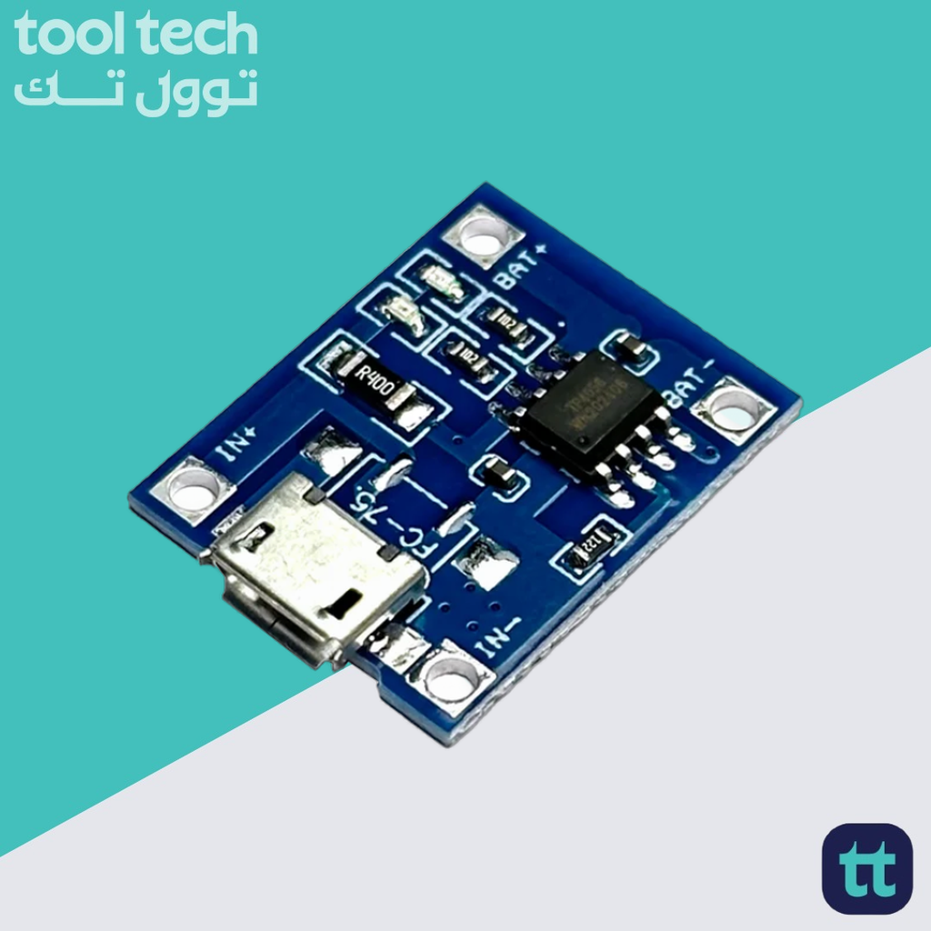
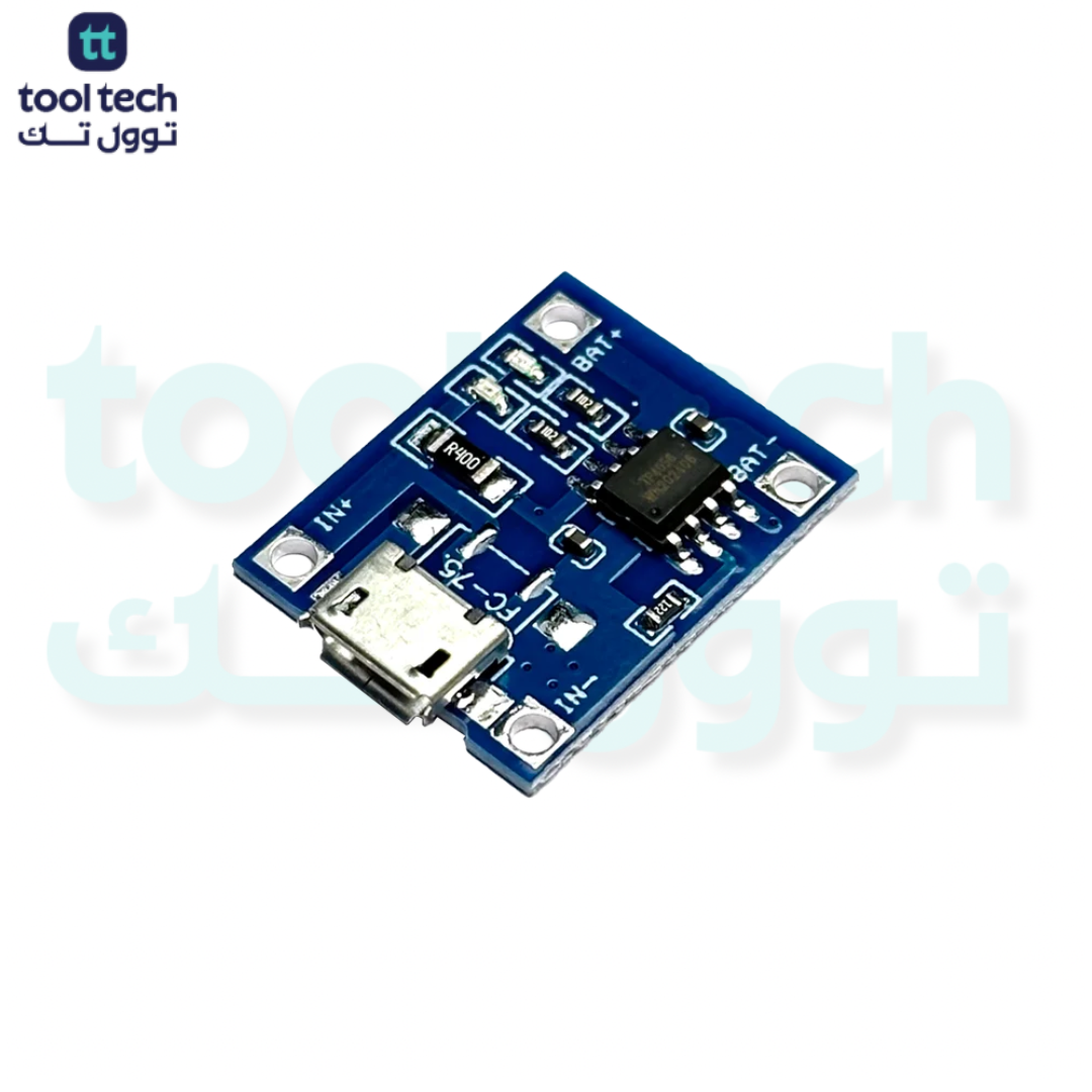
TP4056 Micro-USB Battery Charger Module
The TP4056 Micro-USB Module is the most widely used, cost-effective solution for charging single-cell 3.7V Lithium-ion (Li-ion) or Lithium-polymer (Li-Po) batteries. It is a complete constant-current/constant-voltage (CC/CV) linear charger that fits into a tiny, user-friendly form factor.
Technical Specifications
| Feature | Specification |
| Input Interface | Micro-USB (or solder pads) |
| Input Voltage | 4.5V – 5.5V DC |
| Charging Voltage | 4.2V ± 1.5% |
| Max Charging Current | 1A (Default is usually set to 1A) |
| Protection IC | DW01 / 8205A (on the “with protection” variant) |
| Charging Cutoff | 4.2V |
| Operating Temp | -10°C to +85°C |
How It Works
-
Input: You provide 5V power via the Micro-USB port or the IN+/IN- pads.
-
Charging: The TP4056 chip manages the CC/CV charging cycle. It starts with constant current (CC) to charge the battery quickly, then transitions to constant voltage (CV) to safely “top off” the battery to 4.2V without overcharging.
-
Protection: If your board includes the protection circuit (the extra chip and MOSFETs on the end), it provides three layers of safety:
-
Overcharge protection: Cuts off charging at 4.2V.
-
Over-discharge protection: Cuts off battery output at 2.4V–3.0V to prevent cell damage.
-
Short-circuit protection: Instant power cut if an electrical short is detected.
-
Key Features
-
LED Indicators: Typically, a Red LED turns on while charging, and a Blue (or Green) LED turns on when charging is complete.
-
Adjustable Current: The charge current is set by an onboard resistor (RPROG). By default, it is set to 1A. You can change this resistor if you need to charge smaller capacity batteries (e.g., changing it to 500mA or 200mA).
-
Small Footprint: Its compact size allows it to be easily integrated into small handheld projects or 3D-printed enclosures.
Important Installation & Safety Guidelines
-
Polarity Check: Always verify that the battery leads (B+ and B-) are soldered to the correct pads. Connecting the battery backward can permanently damage the IC.
-
Solder Pads: The input can be powered by either the Micro-USB port or by soldering 5V wires directly to the IN+ and IN- pads.
-
Heat Dissipation: During 1A charging, the TP4056 chip will become hot. This is normal, but ensure the board has some airflow.
-
Charger Source: Always use a stable 5V power source. Using a low-quality or fluctuating power supply can lead to inconsistent charging results.
















Reviews
There are no reviews yet.