




Description
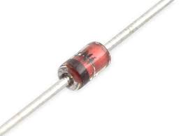
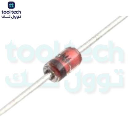
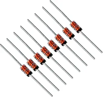
The 18V Zener diode is a standard component for voltage regulation and surge protection. Depending on your specific circuit needs, these are primarily available in two power ratings.
Technical Specifications
| Parameter | 0.5W (Signal Level) | 1.0W (Power Level) |
| Nominal Zener Voltage ($V_Z$) | 18V | 18V |
| Power Dissipation ($P_D$) | 0.5W | 1.0W |
| Common Part Numbers | 1N5248, BZX79-C18 | 1N4746, BZX85-C18 |
| Typical Package | DO-35 (Small Glass) | DO-41 (Larger) |
How a Zener Diode Works
A Zener diode is designed to operate in the reverse breakdown region. When the voltage across the diode reaches its breakdown threshold (18V), it begins to conduct electricity, effectively “clamping” the voltage at that level.
In a shunt regulator circuit, the Zener diode is placed in parallel with your load. To prevent the diode from drawing infinite current and destroying itself, a series current-limiting resistor ($R_s$) is required between the voltage source and the diode.
Selection and Safety Guidelines
-
Physical Sizing: When replacing a component, match the package size. A smaller glass body (DO-35) usually indicates a 0.5W rating, while a larger body (DO-41) usually indicates 1W. Using a higher-wattage diode is generally safe (it has more thermal mass), but ensure it fits your PCB layout.
-
Thermal Limits: To ensure the diode remains within its safe operating temperature, you must limit the current ($I_Z$) flowing through it.
-
For a 0.5W diode: $I_{Zmax} \approx 27mA$
-
For a 1.0W diode: $I_{Zmax} \approx 55mA$
-
-
Failure Modes: If the Zener diode fails, it most commonly shorts out. If your circuit voltage suddenly drops to 0V or a fuse blows, the Zener is a primary component to test with a multimeter.













Reviews
There are no reviews yet.