

Description
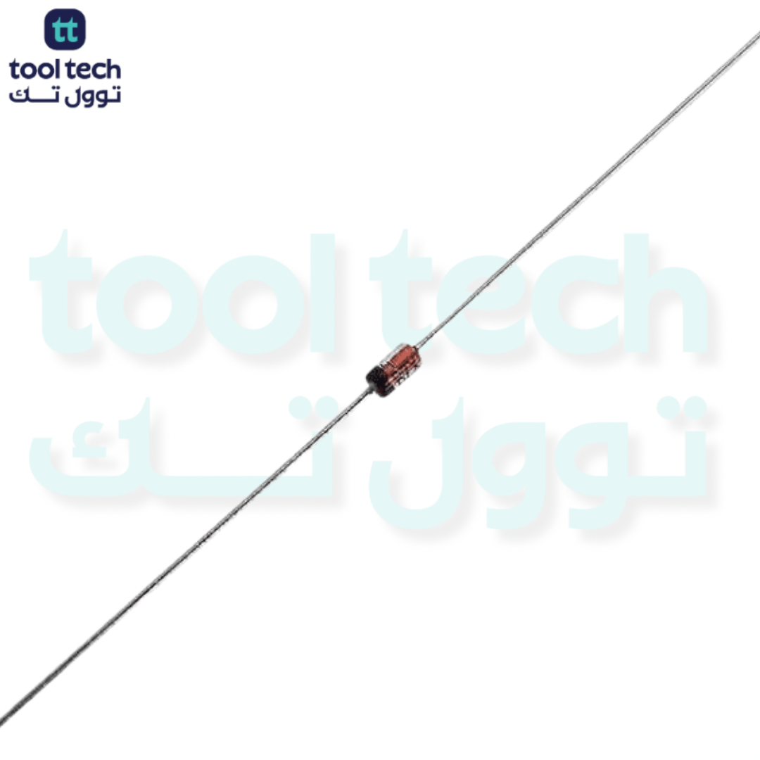
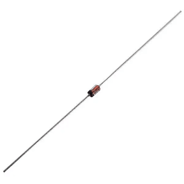
The 3V Zener diode is a standard component for voltage regulation and signal protection, frequently used to establish a stable reference in low-voltage circuits. While “3V” is the nominal target, these are most commonly available as 3.0V or 3.3V parts.
Technical Overview
For a 3V requirement, the most common standard part is the 1N5225 (3.0V) or the BZX79-C3V0. These are standard 500mW devices used for clamping or biasing.
Technical Specifications
| Parameter | Specification |
| Nominal Zener Voltage ($V_Z$) | 3.0V |
| Power Dissipation ($P_D$) | 0.5W (500mW) |
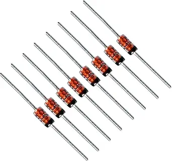
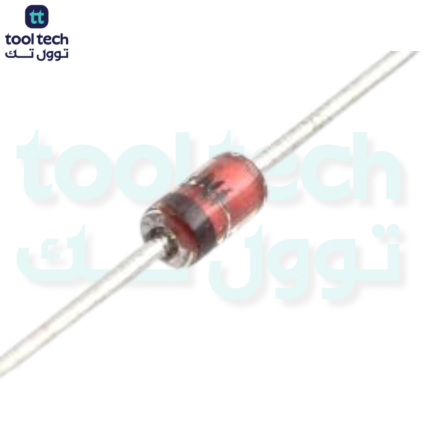
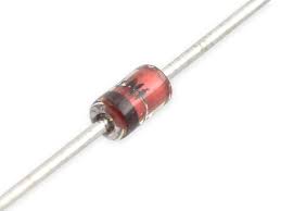
| Package Type | DO-35 (Glass Axial Lead) |
| Tolerance | $\pm 5\%$ |
| Operating Temperature | -65°C to +200°C |
Operating Principle
Like other Zener diodes, this component is designed to operate in the reverse breakdown region. It effectively “clips” or clamps voltage spikes that exceed 3.0V.
To function as a regulator, you must install the diode in reverse bias (cathode toward the positive potential) and include a series current-limiting resistor ($R_s$). This prevents the diode from drawing excessive current, which would exceed its 0.5W power rating and cause it to fail.
Procurement and Application Tips
-
Purchasing (10 pcs): When sourcing in small quantities, search for the part number “1N5225” or “BZX79-C3V0”. Both are widely available through electronics distributors in packs of 10 or more.
-
Thermal Safety: For a 3.0V 0.5W device, the maximum current ($I_Z$) should stay well below $166mA$ ($P / V = 0.5W / 3V$). In practical application, staying under 100mA is recommended for long-term reliability.
-
Component Verification: If you are building a prototype with these 10 pieces, ensure your series resistor is sized correctly for your power source. Using the wrong resistor value is the most common cause of Zener diode failure during the testing phase.













Reviews
There are no reviews yet.