

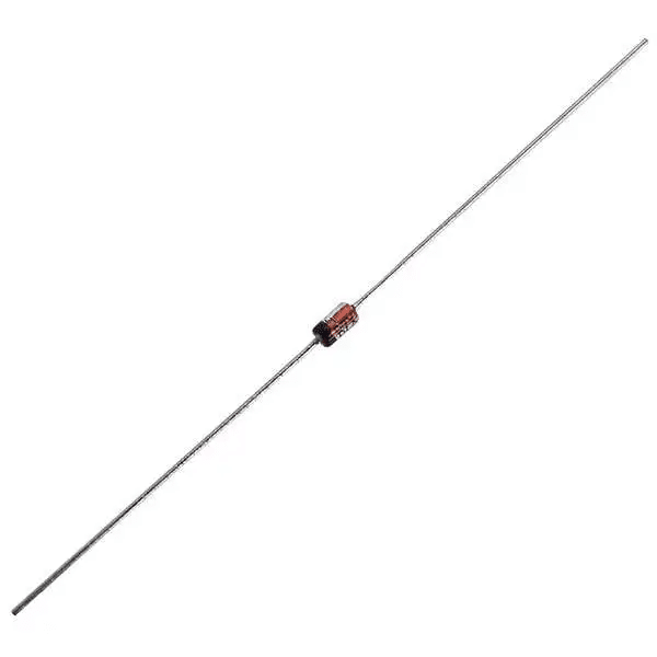


Description
The marking “4.7V” indicates a Zener diode with a nominal Zener voltage ($V_Z$) of 4.7V. This is a staple value in electronics, frequently used to provide a stable reference voltage for analog circuits or to protect sensitive 5V logic inputs from transient overvoltage.
Technical Specifications
| Parameter | Specification |
| Nominal Zener Voltage ($V_Z$) | 4.7V |
| Power Dissipation ($P_D$) | 0.5W (500mW) |
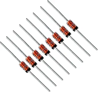
| Package Type | DO-35 (Glass Axial) |
| Tolerance | $\pm 5\%$ |
| Common Part Numbers | 1N5230, BZX79-C4V7 |
How it Works
A Zener diode is designed to operate in the reverse breakdown region. Unlike a standard diode, which blocks current in reverse, a Zener diode is specifically engineered to “break down” at a precise voltage. When the input voltage exceeds 4.7V, the diode begins to conduct, shunting the excess current to ground and holding the voltage across its terminals at 4.7V.
To implement this effectively, you must place the Zener in parallel with the load and include a series current-limiting resistor ($R_s$) between the voltage source and the diode.
Design & Safety Notes
-
Thermal Management: With a 500mW rating, you must ensure the current ($I_Z$) through the diode does not exceed the limit. Using the formula $I_{Zmax} = P_D / V_Z$, your maximum current should be kept well below ~106mA ($0.5W / 4.7V$).
-
Placement: For data signal protection, place the diode as close as possible to the input pin of the chip you are protecting to minimize lead inductance, which can reduce the effectiveness of the clamping during high-speed transients.
-
Troubleshooting: If the voltage on your 4.7V rail is collapsing, use a multimeter to check the Zener. A failed diode usually shorts to ground, causing the rail voltage to drop to 0V.















Reviews
There are no reviews yet.