


Description
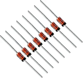
The BZX79-C10 is a highly popular, industry-standard 10V Zener diode, commonly used for voltage regulation and transient voltage suppression in small-signal electronic circuits.
Technical Specifications
| Parameter | Specification |
| Nominal Zener Voltage ($V_Z$) | 10V |
| Power Dissipation ($P_D$) | 500mW (0.5W) |
| Package Type | DO-35 (Glass Axial Lead) |
| Tolerance | $\pm 5\%$ |
| Zener Impedance ($Z_Z$) | 20 $\Omega$ (at $I_Z = 5mA$) |
Understanding the Zener Principle
The BZX79-C10 is designed to operate in the reverse breakdown region. Once the reverse voltage applied across the diode reaches approximately 10V, it enters a state of conduction, clamping the voltage at that level by shunting excess current.
To use this as a voltage regulator, you must connect the diode in reverse bias (banded end toward the positive voltage) and place a series current-limiting resistor ($R_s$) before the diode. This resistor is essential; it limits the current flowing through the diode to ensure the 500mW power limit is not exceeded.
Application & Safety Guidelines
-
Thermal Management: To keep the device safe, use the formula $I_{Zmax} = P_D / V_Z$. For this 10V/0.5W device, your maximum current should be kept below 50mA ($0.5W / 10V$).
-
Circuit Design Tip: To ensure stability, it is standard practice to maintain a small “test current” (typically 5mA for this model) to ensure the diode stays in the linear part of its breakdown region.
-
Testing: If a circuit is failing, you can test the BZX79-C10 using a multimeter. In a healthy state, it will act like a standard diode in forward bias (approx. 0.6V–0.7V) and block current in reverse bias until 10V is reached. A short-circuited diode will measure near 0 ohms in both directions.












Reviews
There are no reviews yet.