


Description
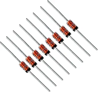
The BZX79-C12 is a widely utilized 12V Zener diode, frequently employed in industrial and consumer electronics for voltage regulation, signal clipping, and as a stable reference voltage for transistor-based circuits.
Technical Specifications
| Parameter | Specification |
| Nominal Zener Voltage ($V_Z$) | 12V |
| Power Dissipation ($P_D$) | 500mW (0.5W) |
| Package Type | DO-35 (Glass Axial Lead) |
| Tolerance | $\pm 5\%$ |
| Zener Impedance ($Z_Z$) | 25 $\Omega$ (at $I_Z = 5mA$) |
Operational Overview
The BZX79-C12 is designed to function in the reverse breakdown region. Once the applied reverse voltage reaches the 12V threshold, the diode transitions into a conductive state, effectively clamping the voltage by shunting excess current to ground.
To implement this as a regulator, you must connect the diode in reverse bias (the cathode/banded side connected to the positive supply) and use a series current-limiting resistor ($R_s$). The resistor is vital; it ensures that the current flowing through the Zener diode does not exceed its 500mW power capacity, which would otherwise result in catastrophic thermal failure.
Application & Safety Guidelines
-
Thermal Management: Using the power formula $P_D = V_Z \times I_Z$, you can calculate the maximum current limit: $I_{Zmax} = 0.5W / 12V \approx$ 41.6mA. For longevity, it is recommended to operate well below this maximum value.
-
Circuit Stability: To achieve the best regulation performance, the circuit should be designed so that the diode remains within its active breakdown region even under varying load conditions.
-
Troubleshooting: When testing with a multimeter, the BZX79-C12 should behave like a standard diode (approx. 0.6V–0.7V forward drop) in forward bias. In reverse bias, it should block current flow at low voltages. If it measures near 0 ohms in both directions, the device has been damaged by overcurrent or overheating.














Reviews
There are no reviews yet.