


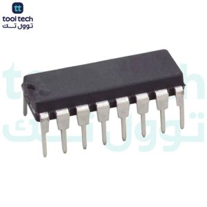
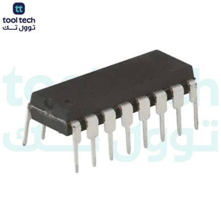
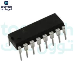
Description
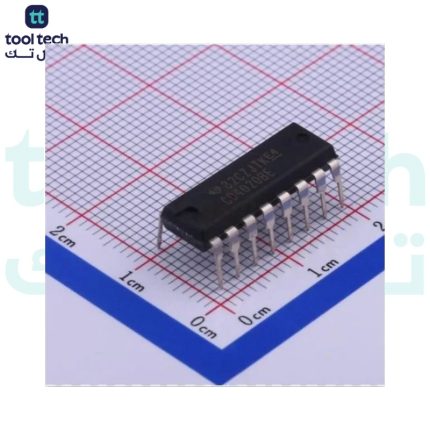
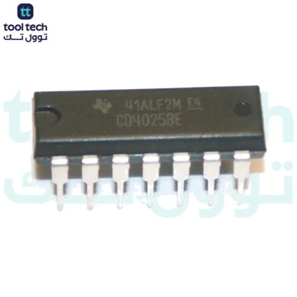
CD4046
is a Micropower Phase-Locked Loop (PLL) that comes with a phase detector for comparing the phase of the output signal with the input signal and adjusting them in order to make the matching signals from both ends.
It comes with a common comparator input and a common signal input amplifier between a low-power linear voltage-controlled oscillator (VCO) and two different phase comparators.
The input signal can be operated in two ways: capacitively layered with a self-biasing amplifier for creating a small voltage signal or directly coupled for a large voltage signal.
The VCO (Voltage Controlled Oscillator) is an integral part of the IC that mainly generates oscillated frequency based on the applied input. The generated frequency is then used for phase modulation.
The chip features two phase comparators i.e. Phase Comparator I and Phase Comparator II. They are also known as Phase Detectors.
Phase comparator I is nothing but an exclusive OR gate that produces a digital, maintaining 90° phase shifts at the VCO.
It is important to note that both signal input and comparator input are set at 50% duty cycle where Phase Comparator I can lock the input frequencies that match with the magnitude of the VCO center frequency.
Similarly, Phase comparator II is known as an edge-controlled digital memory network and maintains a 0° phase shift between signal input and comparator input, providing a lock-in and digital error signal.
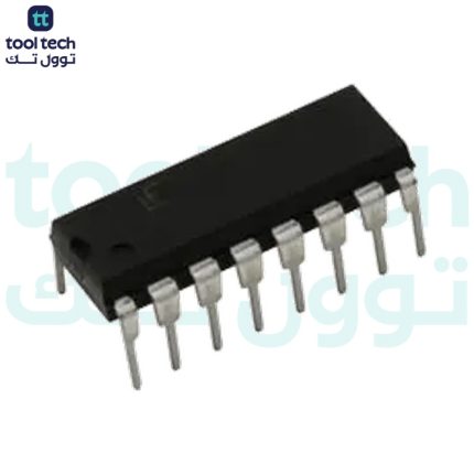
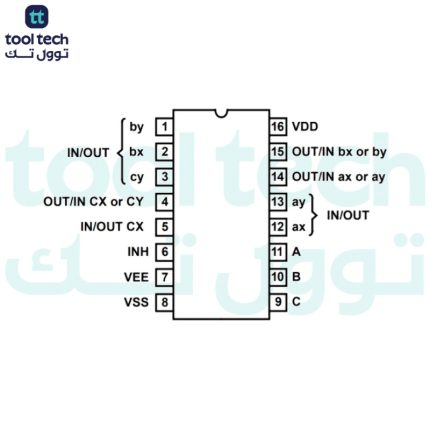
Pin No
Pin Name
Description
1
Phase Pulse
Phase pulse applied to the IC
2
Phase- Comp I Out
the output of Phase Comparator I
3
Comparator IN
Input at the Comparator
4
VCO OUT
Output Signal at VCO
5
INHIBIT
electronically turn on or off the output voltage
6
C1A
Capacitor 1 connected to VCO
7
C1B
Capacitor 2 connected to VCO
8
VSS
source supply
9
VCO IN
Input Signal at VCO
10
D- OUT
Extracting the original signal
11
R1
Resistor 1 connected between VCO and Supply Voltage
12
R2
Resistor 2 connected between VCO and Supply Voltage
13
Phase- Comp II OUT
Generated oscillated output at Phase II Comparator
14
Signal IN
Input Signal applied to the Phase Comparator I
15
Zener
Zener diode for voltage regulation
16
VDD
Drain supply
Technical Specifications
Physical
Case/Package
PDIP
Contact Plating
Gold
Mount
Through Hole
Number of Pins
16
Technical
Frequency
2.4 MHz
Input
CMOS
Max Frequency
2.4 MHz
Max Operating Temperature
125 °C
Max Supply Voltage
18 V
Min Operating Temperature
-55 °C
Min Supply Voltage
3 V
Nominal Supply Current
10 mA
Number of Bits
1
Number of Circuits
1
Number of Elements
1
Number of Gates
1
PLL
Yes
Voltage
20 V
Applications
FM demodulator and modulator
Frequency synthesis and multiplication
Frequency discrimination
Data synchronization and conditioning
Voltage-to-frequency conversion
Tone decoding
FSK modulation
Motor speed control
Datasheet













Reviews
There are no reviews yet.